COPY RIGHTS : TO AVOID COPYRIGHT VIOLATIONS, ALL POSTS ARE SHOWN ALONG WITH SOURCES FROM WHERE ITS TAKEN. PLEASE CONTACT ME IN MY EMAIL SALEEMASRAF@GMAIL.COM , IF YOU ARE THE AUTHOR AND YOUR NAME IS NOT DISPLAYED IN THE ARTICLE.THE UNINTENTIONAL LAPSE ON MY PART WILL BE IMMEDIATELY CORRECTED.

I HAVE SHARED ALL MY PRACTICAL WATER TREATMENT EXPERIENCES WITH SOLVED EXAMPLE HERE SO THAT ANYBODY CAN USE IT.

SEARCH THIS BLOG BELOW FOR ENVO ,COMPACT STP,ETP,STP,FMR,MBBR,SAFF,IRON,ARSENIC,FLUORIDE,FILTER,RO,UASB,BIO GAS,AERATION TANK,SETTLING TANK,DOSING,AMC.

SEARCH THIS BLOG

Showing posts with label solid waste. Show all posts

Wednesday, March 22, 2017

SOLID WASTE MANAGEMENT IN VARIOUS INDIAN CITIES

 SOLID WASTE MANAGEMENT IN VARIOUS INDIAN CITIES  .TAKEN  FROM  DOWN TO EARTH  MAGAZINE  (CSE)
 You can visit  the original source the read the  full article.

Decentralised treatment options introduced in new rules.

The earlier rules relied on costly centralised facilities for treating and disposing municipal wastes while approximately 50 per cent of it can be easily turned into compost at the local level. Thus, the draft rules have made the much-needed provision for providing incentives to decentralised waste treatment facilities. 

Dear All,

First of all, I would like to ofeer Thanks for incorporating few new aspects like involvement of Informal Sectors (especially the Scrap Dealers) and also emphasising the Decentralised Composting and the Collection of Users' Charge. 
However, I would like to know the scopes for the following too .... 
(a) Adequate provisions with added importance on the Health Concern fo the Waste Pickers / Handlers, be it in case of House to House Collection of Segregated Solid Wastes or the Decentralised Composting or waste trasformation in the Informal Sectors like Scrap Dealers.
(b) Decentralisaion of all others aspects like Source Management, Collection, Segragation, Waste Transformation, M&E etc. apart from that in Composting.
(c) Emphasising the Labour intensive Approach for the decentralised activities, alongwith demotivating the highly mechanised process.
(d) Full stop for the unsustained Waste to Energy Approaches.
(c) Strict efforts for Monitoring and Evaluation

Proper redress for the abovesiad issues may eventually make the whole Solid Waste Management Approach more meaningful and result oriented.
Hoping for the Best and all success for "Near Zero" to "Zero Waste Plan" under each Municipalities.
Thanks and Regards.
Nripendra Kumar Sarma
Guwahati, Assam, India

Decentralised integrated solid waste, waste water and solar energy project at New Motibagh, New Delhi


Waste Water Management: About 70% of the 8 lakh litres of water supplied to the residents, that is, 5.6 lakh litres of waste water generated is treated in a decentralized waste water treatment plant within the campus using the Moving Bed Bio-reactor (MBBR) technology. There is a net savings of Rs.5 lakhs per annum due to direct and indirect savings from a decentralized Waste Water Treatment plant (WWTP) in the campus whose running cost is Rs.55.55 lakhs as opposed to the centralized sewerage system costing Rs.60.62 lakhs.  

The energy savings from 300 solar street lights at the GPRA complex, covering internal roads, common areas, parking lots and bunglows, help in saving Rs.32.28 lakhs per annum. Along with solar water heaters, the savings on electricity is close to Rs.35 lakhs a year.    

Therefore, a decentralised integrated solid waste, waste water and energy project for about 1000 households can achieve clean and green surroundings and financial savings to the tune of Rs.40-50 lakhs per annum

Garbage to gold  at mumbai

Though Gowariker and his colleagues are confident of the technology, they caution that refuse pelletisation is not the only or best way to deal with the growing urban garbage problem. Gowariker points out, "A product mix of compost and fuel pellets may be more appropriate, depending on the financial situation and the demand."

Delhi’s solid waste: a systemic failure

What can Delhi do?
We need hybrid solutions. We need a landfill, but only for rejects and inerts. We need waste to energy, but then such plants should ensure that they run on segregated waste only. With over 50 per cent biodegradable waste, there is high potential to compost or generate biogas out of the segregated wet waste. And all this cannot work, unless we segregate at source. With over thousands of crores being spent on collection and transportation, time has come to think out of the box. We can learn from our neighbours and cities across India that are doing commendable work on waste management.
Look at the Alleypey model, where residents have taken it upon themselves to segregate and treat waste at source. It is the best model in the country on decentralised waste management. We can even look at Panjim; the municipal corporation not only ensures segregation at source, but also segregates dry waste into 30 different categories. And then there is Mysuru, Suryapet, Bobbili and a lot of other cities that are doing commendable work. They have adopted local solutions, not global to become zero-waste cities. The CSE has documented cities that are doing commendable work on waste management.

Government notifies new solid waste management rules


Segregation at source should therefore be at the heart of municipalities’ solid waste management system. The only city that has truly adopted segregation is Panaji. Municipal officials have ensured a citywide system that is designed to collect household waste on different days for different waste streams. This ensures separation. It is combined with penalties for non-segregated waste and has promoted colony-level processing as well. Most importantly, for the bulk of commercial establishments such as hotels it has a bag-marking system so that any non-compliance can be caught and fined.

In Kerala’s Alappuzha segregation happens differently. Here the municipality does not collect waste because it has no place to take it to for disposal. The city’s only landfill has been sealed by villagers who live in its vicinity. This withdrawal of the municipality from waste management has meant that the people have to manage their waste, or be drowned in it. They segregate and compost what they can. The compost is used for growing vegetables and plants in their homesteads. The problem is how to handle all the non-biodegradable waste—paper, plastic, aluminum tins, etc. This is where the government has stepped in. It promotes collection through the already well-organised informal waste-recycling sector. The municipality has ended up saving a huge capital cost it would have otherwise incurred for collection and transportation.


Waste smart cities  http://www.downtoearth.org.in/coverage/waste-smart-cities-54119


Tuesday, June 28, 2016

Bio Gas plant from Kitchen Waste and other bio degradable solid waste


Bio Gas plant from Kitchen Waste and other bio degradable solid waste

Proven on wide range of wastes and feedstocks including
  • Livestock and agricultural wastes
  • Biomass
  • Sewage and industrial sludges
  • MSW and catering wastes
  • Food industry wastes
  • Vegetable market waste
  • Restaurant Waste
  • Farm House/Cattle manure waste
  • Slaughter House/Tannery waste
  • Presumed waste
Suitable locations for installation of plant
Hotel premises, army/big establishment canteens (private/ government), residential schools/colleges, housing colonies, religious places / temple trusts, hospitals, hotels, sewage treatment plants, villages, etc.


The Principle:

Add bio degradable Solid waste to a  mixer to process the waste before putting it into predigestor tank. The waste is converted in slurry by mixing with water  in this mixture.
Use of thermophilic microbes for faster degradation of the waste. The growth of thermophiles in the predigestor tank is assured by mixing the waste with hot water and maintaining the temperature in the range of 55-60oC. The hot water supply is from a solar heater. Even one-hour sunlight is sufficient per day to meet the needs of hot water.
After the predigestor tank the slurry enters the main tank where it undergoes mainly anaerobic degra-dation by a consortium of archae-bacteria belonging to Methanococcus group. These bacteria are naturally present in the alimentary canal of ruminant animals (cattle). They produce mainly methane from the cellulosic materials in the slurry.
The undigested lignocellulosic and hemicellulosic materials then are passed on in the settling tank. After about a month high quality manure can be dug out from the settling tanks. There is no odour to the manure at all. The organic contents are high and this can improve the quality of humus in soil, which in turn is responsible for the fertility.
As the gas is generated in the main tank, the dome is slowly lifted up. This gas is a mixture of methane (70-75%), carbondioxide (10-15%) and water vapours (5-10%). It is taken through GI pipeline to the lamp posts. Drains for condensed water vapour are provided on line. This gas burns with a blue flame and can be used for cooking as well.
The gas generated in this plant is used for gas lights fitted around the plant. The potential use of this gas would be for a canteen. The manure generated is high quality and can be used in fields.


This manure can be supplied to farmers at the rate of 4-5 Rs. per Kg. Alternatively municipal gardens and local gardens can be assured of regular manure from this biogas plant.


Thursday, December 24, 2015

How to make your own HOME BIO GAS PLANT FROM KITCHEN WASTE

KITCHEN (FOOD) WASTE---SMALL MODULAR BIO GAS SYSTEM FOR INDIVIDUAL HOUSES

How much Kitchen Waste do we have to feed on daily basis?

Kitchen waste is high calorie feedstock which contains starch, sugar, cellulose or protein. This material is capable of producing more quantity of methane per ton of feedstock (on dry weight basis). Care must be taken to ensure that kitchen waste like vegetable pcs, leaves, wheat roti / bread or solid left overs are converted in semi liquid form before feeding in the Plant. This can be done either by using food crusher or keeping kitchen waste in Bucket with water for 4 to 5 hours prior to feeding.
  DATA CHART :
Gas Generation Capacity
SIZE OF TANKS (PVC)
Mix Kitchen Waste / day
Water / day
Initial Cow Dung charging
DIA
HEIGHT
0.5 Cu. Mtr
1600
1100
2.5 Kg
2.5 Litrs of Water
20 Kg
1.0 Cu. Mtr
2100
1500
5 Kg
5 Litrs of Water
25 Kg
1.5 Cu. Mtr
2300
1650
10 Kg
10 Litrs of Water
30 Kg
2.0 Cu. Mtr.
2550
1800
20 Kg
20 Litrs of Water
35 Kg

Gas Volume :
One Cu. Mtr. Bio Gas runs approximately 1 Hour at a time. One can cook three meals per day by using 1 cum Bio Gas Plant.
We can use Bio Gas frequently about three times a day with the interval of around 2 to 3 hours.1 cum of bio gas is equal to 0.43 kg of LPG. About 5 kg. of kitchen waste is required for 1 cum. plant. Gas coming out of the plant can be used in the kitchen with the help of biogas stove while the slurry coming out from the outlet can be used as manure. The gas generated will have 60 to 70% methane, 5 to 10% water vapour (moisture) and the balance will be Carbon-di-oxide.

How it works :

The main digester is initially fed with fresh cow dung slurry so that slurry comes out from the slurry outlet pipe. The ratio of dung and water should be 1:1 Subsequently, cattle dung is not needed. Now wait for bio gas production to start in the newly installed plant. It may take 2-3 days for the first production of gas.
As gas starts producing, one can start feeding the plant daily with  kitchen / vegetable waste in a small quantity and increase it to the recommended quantity after one week.. The ratio of kitchen waste and water should be 1:1.This will facilitate easy flow of waste through inlet  into  the  bio-methanization  plant.  The  value  of    pH  of  the  kitchen  waste  should  be ideally kept  at 7 for optimum production of biogas. Make a slurry of lime by adding one kg lime with 10 liter of water and add it into the digester chamber to make pH 7. Check with pH paper whether the pH is 7 or not regularly.
LOCATION:  Always in a sunny area where temperature is high and as near to kitchen as possible so that gas pipe length is less.

OPERATING COST : The operating cost of Bio Gas plant is very less.  All what required for 1 Cu. Mtr Bio Gas plant is  5 to 6 Kg of Kitchen waste / on dry weight basis. Break even period is approximately 5 to 6 years if Gas is used for cooking application                                  

CONTACT US ENVO PROJECTS Mobile: 09899300371

Mini Bio-gas plant using food waste, decomposable organic material and kitchen waste

Source Of The Article: http://www.instructables.com/id/Bio-gas-plant-using-kitchen-waste/
Components of the Bio-gas Plant

The major components of the bio-gas plant are a digester tank, an inlet for feeding the kitchen waste, gas holder tank, an outlet for the digested slurry and the gas delivery system for taking out and utilizing the produced gas.

This project is also useful for students to have a hands-on learning experience in constructing a Mini Bio-Gas Plant, using locally available material.

Material Required:

1. Empty PVC can 50 ltrs capacity: 1 No. (to be used as Digester Tank)
2. Empty PVC can 40 ltrs capacity: 1 no. (to be used as Gas Holder Tank) (Make sure the smaller can fits inside larger one and moves freely)
3. 64 mm dia pvc pipe: about 40 cm long (to be used for feeding waste material)
4. 32 mm dia pvc pipe: about 50 cm long (fixed inside gas holder tank as a guide pipe)
5. 25 mm dia pvc pipe: about 75 cm long (fixed inside the digester tank as a guide pipe)
6. 32 mm dia pvc pipe: about 25 cm long (fixed on digester tank to act as outlet for digested slurry)
7. M-seal or any water-proof adeshive
8. Gas outlet system: Please see Step 4 below for required materials and construction

Tools required

Do not require many tools here. A hack saw blade for cutting the cans & pipes and a sharp knife for cutting holes on the cans are all the tools we need.

Additional accessories

A single burner bio-gas stove or a Bunsen Burner used in school laboratories
Initially, cow-dung mixed with water will be fed in to the system, which will start the gas formation process. Subsequently, food waste, decomposable organic material and kitchen waste will be diluted with water and used to feed the system. The gas holder will rise along the guide pipes based on the amount of gas produced. We can add some weight on top of the gas holder to increase the gas pressure. When we feed the system, the excess digested slurry will fall out through the outlet pipe, which can be collected, diluted and used as organic manure.

Initial production of gas will consist of oxygen, methane, carbon di oxide and some other gases and will not burn. These gases can be released to the atmosphere by opening the ball valve at least three / four times.

Subsequent gas will consist of about 70 to 80 percent methane and the rest carbon di oxide, which can be used in a single bio-gas burning stove or a Bunsen burner.

Total cost of this proto-type system is about one thousand Indian Rupees (about 20 dollars)
Gas formation started and the gas holder tank gets lifted up. I have placed two bricks on top of the gas holder to get more gas pressure.

Note for students who are doing this as their School Project:

1. Take guidance from your teacher while using the gas in a stove or Bunsen burner.
2. Collect surplus food and wastage during lunch, dilute and feed the system.
3. Fruit peels, extracted tea powder, waste milk and milk products  can also be used for feeding the system.
4. DO NOT USE eggshells, Onion peels or left-over bones in this system as they will affect the efficient functioning of the system
5. Plant some seedling
6. while feeding, collect the slurry from the outlet, feed the seedlings and watch them grow

Read step by step instruction at: http://www.instructables.com/id/Bio-gas-plant-using-kitchen-waste/


Components of the Bio-gas Plant

The major components of the bio-gas plant are a digester tank, an inlet for feeding the kitchen waste, gas holder tank, an outlet for the digested slurry and the gas delivery system for taking out and utilizing the produced gas.


This project is also useful for students to have a hands-on learning experience in constructing a Mini Bio-Gas Plant, using locally available material.


Material Required:


1. Empty PVC can 50 ltrs capacity: 1 No. (to be used as Digester Tank)

2. Empty PVC can 40 ltrs capacity: 1 no. (to be used as Gas Holder Tank) (Make sure the smaller can fits inside larger one and moves freely)
3. 64 mm dia pvc pipe: about 40 cm long (to be used for feeding waste material)
4. 32 mm dia pvc pipe: about 50 cm long (fixed inside gas holder tank as a guide pipe)
5. 25 mm dia pvc pipe: about 75 cm long (fixed inside the digester tank as a guide pipe)
6. 32 mm dia pvc pipe: about 25 cm long (fixed on digester tank to act as outlet for digested slurry)
7. M-seal or any water-proof adeshive
8. Gas outlet system: Please see Step 4 below for required materials and construction

Tools required


Do not require many tools here. A hack saw blade for cutting the cans & pipes and a sharp knife for cutting holes on the cans are all the tools we need.


Additional accessories


A single burner bio-gas stove or a Bunsen Burner used in school laboratories

Initially, cow-dung mixed with water will be fed in to the system, which will start the gas formation process. Subsequently, food waste, decomposable organic material and kitchen waste will be diluted with water and used to feed the system. The gas holder will rise along the guide pipes based on the amount of gas produced. We can add some weight on top of the gas holder to increase the gas pressure. When we feed the system, the excess digested slurry will fall out through the outlet pipe, which can be collected, diluted and used as organic manure.

Initial production of gas will consist of oxygen, methane, carbon di oxide and some other gases and will not burn. These gases can be released to the atmosphere by opening the ball valve at least three / four times.


Subsequent gas will consist of about 70 to 80 percent methane and the rest carbon di oxide, which can be used in a single bio-gas burning stove or a Bunsen burner.


Total cost of this proto-type system is about one thousand Indian Rupees (about 20 dollars)

Gas formation started and the gas holder tank gets lifted up. I have placed two bricks on top of the gas holder to get more gas pressure.

Note for students who are doing this as their School Project:


1. Take guidance from your teacher while using the gas in a stove or Bunsen burner.

2. Collect surplus food and wastage during lunch, dilute and feed the system.
3. Fruit peels, extracted tea powder, waste milk and milk products  can also be used for feeding the system.
4. DO NOT USE eggshells, Onion peels or left-over bones in this system as they will affect the efficient functioning of the system
5. Plant some seedling
6. while feeding, collect the slurry from the outlet, feed the seedlings and watch them grow 

Step one; 50 ltrs capacity PVC can, which will act as the digester unit and removed the top portion of the can, by cutting it with a hack saw blade: 

Step 2: The smaller white can, which will act as the gas holder fits inside the red one. Here, again removed the top of the white can, also with the help of a hack saw blade:


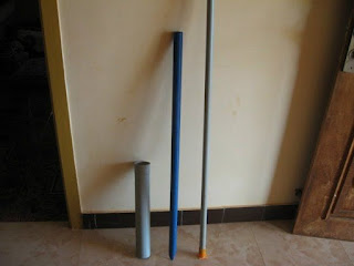
Step 3: 64 mm, 32 mm and 25 mm dia PVC pipes which  will be used for feeding the kitchen waste, guide pipe for the gas holder and guide pipe fixed with the digestion chamber respectively. A small piece of 32 mm dia pipe will be used as outlet for the slurry:

Step 4:

1.  items required for the gas delivery system: got these items from a hardware store


1. Ball valve : one no ( to adjust the gas flow)
2. 'T' joint : one no ( to connect the gas holder and the ball valve)
3. Cap to block one end of 'T' joint : one no
4. Coupling or Adapter : one no (to connect vertical end of 'T' in to the gas collector)
5. Nipple: one no (added to the coupling in to the gas collector)
6. Gas pipe (flexible) : two meters
7. Barb : one no (fitted with the gas pipe, to join with the Ball valve)
8. Clip : one no (used for crimping the barb with the gas pipe and make it leak-proof)
9. Teflon tape : one roll (used as thread tape in all joints)

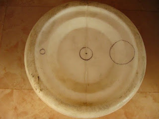
Step 5: Here I have marked the cuts to be made in the bottom of the gas collection tank. The smaller hole on the left for gas delivery system, center hole for fixing the 32 mm guide pipe and 64 mm hole for fixing the waste feeding pipe on the right side. Made these holes with the help of a sharp knife and hack saw blade.


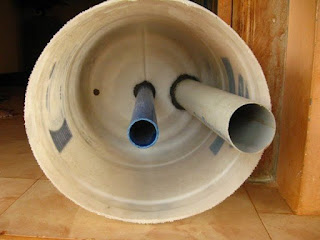
The next image is Inside of the gas holder showing the 32 mm guide pipe (center) and the 64 mm feeding pipe fixed with M-seal

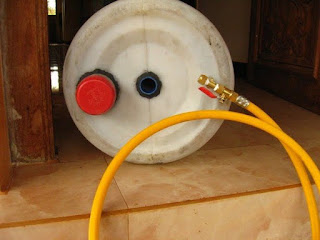
 Step 6: Top view of the gas holder showing the feeding pipe, central guide pipe and the gas delivery system: I have closed the feeding pipe withe an old lid  (red one). This will facilitate opening the feed pipe only during feeding the system.

Step 7: Digestion tank fitted with the central guide pipe and the outlet pipe for the slurry:

Step 8:

Completed unit. I have removed the gas pipe, so that the joints will get cured without any stress:
Step 9:

Charged the digester tank with cow dung diluted with water. Placed the gas holder tank and left it for two three days. The cow dung slurry started the process of gas forming.

Gas formation started and the gas holder tank gets lifted up. I have placed two bricks on top of the gas holder to get more gas pressure.
Step 10:
Note for students who are doing this as their School Project:

1. Take guidance from your teacher while using the gas in a stove or Bunsen burner.
2. Collect surplus food and wastage during lunch, dilute and feed the system.
3. Fruit peels, extracted tea powder, waste milk and milk products  can also be used for feeding the system.
4. DO NOT USE eggshells, Onion peels or left-over bones in this system as they will affect the efficient functioning of the system
5. Plant some seedling
6. while feeding, collect the slurry from the outlet, feed the seedlings and watch them grow

Wait for a day or two before feeding the system, allowing all joints to get cured and become leak-proof.

Initially, cow-dung mixed with water will be fed in to the system, which will start the gas formation process. Subsequently, food waste, decomposable organic material and kitchen waste will be diluted with water and used to feed the system. The gas holder will rise along the guide pipes based on the amount of gas produced. We can add some weight on top of the gas holder to increase the gas pressure. When we feed the system, the excess digested slurry will fall out through the outlet pipe, which can be collected, diluted and used as organic manure.

Initial production of gas will consist of oxygen, methane, carbon di oxide and some other gases and will not burn. These gases can be released to the atmosphere by opening the ball valve at least three / four times.

Subsequent gas will consist of about 70 to 80 percent methane and the rest carbon di oxide, which can be used in a single bio-gas burning stove or a Bunsen burner.

Total cost of this proto-type system is about one thousand Indian Rupees (about 20 dollars)

This is a basic prototype of a Bio-gas system using the food waste, decomposable organic material and kitchen waste to produce gas. An one thousand liter capacity Digestion tank will be sufficient for a small household for daily cooking purpose. The bigger commercial models provide a water seal between the digestion tank and gas holder tank.


You can get further information on kitchen waste based mini Bio-gas plant at the following links


http://www.instructables.com/id/Constructing-a-Medium-Sized-Biogas-Plant-Using-Kit/step3/Other-Materials-Required/


Monday, September 01, 2014

Quantity of Solid Waste Generation

Considering an average garbage generation per capita per day as 0.450 Kg, we can assume a total garbage generation for a population of 100,000 as 45,000 Kg per day

Saturday, September 17, 2011

Landfill Leachate Treatment


Landfill Leachate Treatment

Landfill leachate is generated from liquids existing in the waste as it enters a landfill or from rainwater that passes through the waste within the facility. The leachate consists of different organic and inorganic compounds that may be either dissolved or suspended. An important part of maintaining a landfill is managing the leachate through proper treatment methods designed to prevent pollution into surrounding ground and surface waters


The physical appearance of leachate when it emerges from a typical landfill site is a strongly odoured black, yellow or orange coloured cloudy liquid. The smell is acidic and offensive and may be very pervasive because of hydrogen, nitrogen and sulfur rich organic species such asmercaptans.

If leachates have a distinguishing characteristic, it is that they are variable.  Flows change based on the weather  – increasing during rainy periods, decreasing during dry and waste concentrations can change dramatically over the life of the landfill.   As a result, no landfill leachate is constant over time, and no two leachates are the same.

When the landfill is a few years old the dominated fermentation phase is acidogenic and the leachate generated is generally referred as “young”.In that case, COD and BOD reaches very high concentrations. The ratio of BOD/COD is higherthan 0.7 and pH is low due to the high concentrations VFAs. Landfill grater than 10 years old aregenerally in the methanogenic phase and theleachate generated is referred to as “old”. Duringthe methanogenic phase, bacterias are degradingthe VF-acids and reduce the organic strength ofleachate, leading to the pH value higher than 7.In “old” leachate BOD decreases faster than CODand the radio BOD/COD is stabilized on the levelless than 0.2 [2,4].Anaerobic treatmentprocess is used mainly for young landfill leachate,which BOD5 and BOD5/COD ratio is very high[2]. However, Kettunen, et al. [10] performedthe treatment with UASB reactor were municipal landfill leachate was having COD higher than800 mg × dm−3 and the BOD/COD radio washigher than 0.3.Anaerobic processes of landfill leachate inUASB reactor allow complete removal of CODfrom 65 to 76% and BOD5 removal beyond90% [11].


Table 1

Characteristics of landfill leachate 

Parameter Value

COD, mg O2 × dm−3 3500–4200

BOD5, mg O2 × dm−3 380–420

pH 8.2–8.4

Alkalinity mg CaCO3 × dm−3 4900–5200

Chloride mg Cl−× dm−3 1800–2500

Ammonia nitrogen, mg NH4+× dm−3890–994

VFA, mg CH3COOH × dm−3 500–900

landfill leachate  quantity , 5%

UNITS OF TREATMENT OF LANDFILL LEACHATE:

1.      Collection Sump: Areas in which rainfall is higher than average typically have larger sumps. A further criterion for sump planning is accounting for the pump capacity. The relationship of pump capacity and sump size is inversed. If the pump capacity is low, the volume of the sump should be larger than average. It is critical for the volume of the sump to be able to store the expected leachate between pumping cycles. This relationship helps maintain a healthy operation. Sump pumps can function with preset phase times. If the flow is not predictable, a predetermined leachate height level can automatically switch the system on. Other conditions for sump planning are maintenance and pump drawdown. Collection pipes typically convey the leachate by gravity to one or more sumps, depending upon the size of the area drained. Leachate collected in the sump is removed by pumping.

2.    UASB Reactor:

3.     Clarifier Tank :

4.    Clear Water Tank:

5.     Activated Carbon Filter:


LITERATURE STUDY: WASTE TO ENERGY CONCEPTS


Energy recovery as electric power is a feature of all waste-to-energy systems.

Evaluation of the applicability of the technologies of biomethanation, gasification/pyrolysis,incineration and landfilling as Waste-to-Energy options, and their comparison against composting as a competing technology for waste disposal, has shown the following:

Biomethanation has emerged as a favoured technology for various urban and industrial waste.
Gasification/pyrolysis have a distinct promise, and although there are limitations to its uptake, these can be overcome as the technology matures.
Incineration is a mature technology for energy recovery from urban and industrial wastes and has been sucessfully commercialized in the developed countries. The recent focus has been on environmental compliance due to which it will become an expensive option.
The present trend is in favour of material recovery facilities and a shift away from landfills for MSW disposal in developed countries.
Compositing is not a WTE option and does not come out as worthwhile waste treatment process.
Technologies like landfill with gas recovery and composting can become viable options for certain locations in India, as a short to medium term option.


Landfill Leachate Treatment Technologies

Landfill leachate may be characterized as a water-based solution of four groups of contaminants ; dissolved organic matter (alcohols, acids, aldehydes, short chain sugars etc.), inorganic macro components (common cations and anions including sulfate, chloride, Iron, aluminium, zinc and ammonia), heavy metals (Pb, Ni, Cu, Hg) , and xenobiotic organic compounds such as halogenatedorganics, (PCBs, dioxins, etc.).[4]

Leachate treatment technologies fall into two basic types, biological and physical/chemical. In larger systems and depending on the treatment goals, integrated systems which combine the two are often used.
The typical processes used for pretreatment include equalization, aeration, pH adjustment and metals removal.

The most common biological treatment is activated sludge - a suspended-growth process that uses aerobic microorganisms to biodegrade organic contaminants in leachate. With conventional activated-sludge treatment, the leachate is aerated in an open tank with diffusers or mechanical aerators. After the aeration phase, the mixed liquor of microorganisms and leachate is pumped to a gravity clarifier.
The rotating biological contactor (RBC) is an attached-growth, aerobic, biological treatment process in which a series of discs are partially submerged in a tank of leachate. The disks eventually develop a slime layer, then rotational shear forces strip off the excess solids and carry them with the effluent to a clarifier, where they are settled and separated from the treated waste.
The carbon technique removes dissolved organics from the leachate. Although carbon systems may be useful with some older leachates, the cost of the carbon in the regeneration stage can make the process one of the most expensive treatment options.
Advanced Treatment The new landfill regulations have made some treatment systems obsolete. Many landfill operators are now choosing new systems that produce a cleaner effluent and can reduce capital and operating expenses. Such systems include:
* Recirculation and Injection. Direct recirculation distributes the leachate onto the landfill in a semi-closed loop process. While promising, this system has limitations of recirculating 100 percent of the leachate without literally soaking the landfill.
* Membrane Solution. Membrane technology can be adapted to many steps of purification and keep clean-up standards at a high level. Membranes can remove contaminants without extensive biological infrastructure or toxic chemicals.
* Reverse Osmosis (RO). Prior to 1988, reverse osmosis wasn't able to treat leachate successfully due to the core membrane design of spiral-wound modules, which were state-of-the-art at that time. While this method produced efficient results, it also promoted bio-fouling and premature clogging.
Disc Tube technology, developed by the Rochem Group, has been installed in more than 35 European landfills to treat feed waters that would foul conventional RO configurations. After the contaminated water is fed into the tubular chamber, its flow is controlled as it passes through a system of discs and over flat membrane cushions, removing clean water and concentrating the waste material. The turbulent flow reduces the membranes' tendency to scale or foul and requires cleaning less frequently.
The system removes heavy metals, suspended solids, ammonia and hazardous non-degradable organics including pesticides and herbicides without extensive pre-treatment systems. The pure water is clean enough for direct discharge into the environment and accounts for 75 to 92 percent of the leachate. The remaining concentrate can then be recycled to the landfill or further processed.

Siemens Water Technologies' PACT® systems combine biological treatment (activated sludge) with adsorption (powdered activated carbon) so that physical and biological treatment occur simultaneously. The system removes biodegradable and non-biodegradable pollutants in a single process

The most cost effective form of treatment for high levels of BOD, COD and ammonia is intense biological oxidation, and in the UK the sequential batch reactor is the most common technology used. The sequence batch reactor (SBR) is a form of activated sludge treatment.
Granular activated carbon, in combination with biological pretreatment, is a proven and economical technology which is effective in reducing Chemical Oxygen Demand (COD), Adsorbable Organic Halogens (AOX), pesticides, solvents, organic compounds and other toxic substances to the strictest legal National and EC norms. The chemical composition and content of landfill leachate can vary greatly between landfill sites. The age of the landfill, type of waste and treatment processes already in operation are the parameters to be considered.
COD levels can range from 200mg/l to 2000mg/l. Carbon consumption is normally dependent upon the COD adsorption rather than the AOX. Therefore COD will be the determining factor in estimating carbon consumption.

However, an aerobic system must be used after the UASB reactor for the effluent to meet the standards defined for the proposed disposal method.


Combined treatment of leachate from sanitary landfill and municipal wastewater by UASB reactors

This study showed the potential of anaerobic treatment in an UASB reactor treating a combination of domestic wastewater and leachate in a 5% volumetric ratio of leachate. Under these conditions the reactor assimilated properly the leachate fraction incorporated. With a HRT of 8 h and a mean volumetric organic load of 2.84 kg m(-3) d(-1) COD removal efficiencies around 70% were obtained,
When installing a leachate treatment system, choose a plan that will provide the maximum amount of long-term flexibility to assure compliance with future regulations and discharge standards.
LEACHATE RECYCLE  CONCEPT :The major objective of gas studies is directed towards maximizing production rates of gas by biodegradation of the waste while simultaneously reducing the period of time that gas is evolved by recycling leachate. It describes potential means of managing both leachate quality and quantity by leachate recirculation to aid in decomposition of the waste while also treating the organic material in the leachate and reducing the quantity of leachate that must be treated and hauled away from the site.