COPY RIGHTS : TO AVOID COPYRIGHT VIOLATIONS, ALL POSTS ARE SHOWN ALONG WITH SOURCES FROM WHERE ITS TAKEN. PLEASE CONTACT ME IN MY EMAIL SALEEMASRAF@GMAIL.COM , IF YOU ARE THE AUTHOR AND YOUR NAME IS NOT DISPLAYED IN THE ARTICLE.THE UNINTENTIONAL LAPSE ON MY PART WILL BE IMMEDIATELY CORRECTED.

I HAVE SHARED ALL MY PRACTICAL WATER TREATMENT EXPERIENCES WITH SOLVED EXAMPLE HERE SO THAT ANYBODY CAN USE IT.

SEARCH THIS BLOG BELOW FOR ENVO ,COMPACT STP,ETP,STP,FMR,MBBR,SAFF,IRON,ARSENIC,FLUORIDE,FILTER,RO,UASB,BIO GAS,AERATION TANK,SETTLING TANK,DOSING,AMC.

SEARCH THIS BLOG

Showing posts with label envo projects. Show all posts

Thursday, March 10, 2016

ENVO COMPACT MBBR STP

ENVO COMPACT MBBR STP
ENVO COMPACT 50

OTHER MODELS


PRICE LIST OF COMPACT STP (SEWAGE TREATMENT PLANT)

Capacity
Ex Delhi Cost 
 5  kld
Please contact for price
10 kld
      
25 kld
     
30 kld
     
   
50 kld
     
100 kld
      
Note:
1.Variation from our standard make or standard
design will vary the cost mentioned.
2.All Taxes Extra as applicable
3.All Transportation charges extra as actual.

An introduction to MBBR (moving bed biofilm reactor )/ FM Reactor/ FAB /FMR Reactor wastewater treatment

When communities of microorganisms grow on surfaces, they are called biofilms. Microorganisms in a biofilm wastewater treatment process are more resilient to process disturbances compared to other types of biological treatment processes.  Thus, biofilm wastewater treatment technologies can be considerably more robust especially when compared to conventional technologies like activated suldge process..
In the MBBR biofilm technology the biofilm grows protected within engineered plastic carriers, which are carefully designed with high internal surface area. These biofilm carriers are suspended and thoroughly mixed throughout the water phase. With this technology it is possible to handle extremely high loading conditions without any problems of clogging, and treat industrial and municipal wastewater on a relatively small footprint.

System description

The MBBR™ biofilm technology is based on specially designed plastic biofilm carriers or biocarriers that are suspended and in continuous movement within a tank or reactor of specified volume. The design of associated aerators, grids, sieves, spray nozzles and other integral parts to the reactor is also of great importance in making up the system as a whole .
The industrial and municipal wastewater is led to the MBBR™ treatment reactor where biofilm, growing within the internal structures of the biocarriers, degrade the pollutants.  These pollutants that need to be removed in order to treat the wastewater are food or substrate for growth of the biofilm.  The biocarrier design is critical due to requirements for good mass transfer of substrate and oxygen to the microorganisms  .  Excess biofilm sloughs off the biocarrier in a natural way .

An aeration grid located at the bottom of the reactor supplies oxygen to the biofilm along with the mixing energy required to keep the biocarriers suspended and completely mix within the reactor.

Treated water flows from reactor through a grid or a sieve, which retains the MBBR™ biocarriers in the reactor. Depending on the wastewater, the reactors are may be equipped with special spray nozzles that prevent excessive foam formation.

The MBBR is a biological aerobic degradation of organic pollutants. The process utilizes millions of tiny, polyethylene biofilm elements that provide a high surface area as a home for a vast, highly active bacteria culture. This fixed film process features a flexible reactor design, the ability to handle load increases without the need for extra tankage, and remains stable under large load variations, including temperature, strength or pH. Like the activated sludge process, the MBBR process utilizes the whole volume of an open tank. Unlike an activated sludge reactor, it does not require sludge return to operate effectively. In MBBR , addition of media quantity and Air Quantity is the Key Factor.

Total reactor volume of the MBBRs is designed for different hydraulic retention time for different types of waste water at average flows and than checked against peak flows. Essentially nutrient levels and DO levels are the only control points for the system.


Moving Bed Biofilm Bioreactor (MBBR) process uses the whole tank volume for biomass growth. It uses simple floating media, which are carriers for attached growth of biofilms. Biofilm carrier movement is caused by the agitation of air bubbles. This compact treatment system is effective in removal of BOD as well as nitrogen and phosphorus while facilitating effective solids separation.

Design and Construction Principles

Neutralised and settled wastewater passes through MBBR for reduction in BOD/COD. Most of the MBBR plants are provided with vertically or horizontally mounted rectangular mesh sieves or cylindrical bar sieves. Biofilm carriers are made up of high density (0.95 g/cm3) polyethelene. These are normally shaped as small cylinders with a cross inside and fins outside. The standard filling of carrier is  not more than 465 m2/m3. Generally, design load for COD-BOD removal is 20 g COD / m2d. Smaller carriers need smaller reactor volume at a given loading rate (as g/m2d) when the carrier filling is same. 

It is advisable to use MBBR in combination with a DEWATS  as a pre-treatment unit, depending on the local conditions and input characteristics. It is a very robust and compact alternative for secondary treatment of municipal wastewater, having removal efficiency for BOD 90 – 95% (low rate) and that of 75 – 80% for high rate. Average nitrogen removal is about 85%. There is no need for sludge recirculation. Phosphorus and faecal coliform reduction is feasible with additional passive (non-mechanical) or active (mechanical) system components.


A constantly operating MBBR does not require backwashing or return sludge flows. It has minimal head-loss. Coarse-bubble aeration in the aeration zone in the wastewater treatment tank provides ease of operation at low-cost. Agitation continuously moves the carrier elements over the surface of the screen thus preventing clogging. Maintenance of MBBR system includes screening, influent equalisation, clarifier system, sludge handling and integrated control system. There is no need to maintain f/M ratio as there is self-maintenance of an optimum level of productive biofilm. Skilled labour is required for routine monitoring and operations of pumps and blowers.

Wednesday, January 27, 2016

HOW TO DESIGN A BIO GAS PLANT--- SOLVED EXAMPLE


 FLOW CHART


The two commonly used types of bio-gas plants are:
a) Floating drum type, and
b) Fixed dome type.
The commonly used model of bio-gas plants are: 
a) Floating drum design:
i) KVIC model, 
ii) Pre-fabricated ferro-cement digester model, and 
iii) Pragati model. 
b) Fixed dome type: 
i) Janta model, and 
ii) Deenbandhu model.

Design Parameters taken for  Bio Methanation


·         Feed Substrate Total Solid Concentration(TSC):  8-9 % (For Cow dung)
·         Ratio of Dung to Water: 1:1
·         Bio Gas produced : 0.06 cu mtr / kg dung (Summer 47 degree)
·         0.03 cu mtr / kg dung (winter 8 degree)
·         Temperature : 35 degree centigrade
·         PH – 7-8
·         Retention Time : 30 days (For temp 25-35 Degree Cent)
·         Depth of the plant is between 4 to 6 m according to the size
·         Depth to diameter ratio between 1.0 to 1.3
·         When the digester diameter exceeds 1.6 m, a partition wall is provided in the digester
·         Average gas production from dung may be taken as 40 lit/kg. of fresh dung

·         One Cu. m gas is equivalent to 1000 litres

DESIGN EXAMPLE OF BIO GAS PLANT
http://archive.unu.edu/unupress/unupbooks/80362e/80362E0j.htm
FIG. 3. Chinese Biogas Plant Design
The digester is of standard KIVC design, consisting of a cylindrical underground chamber using 23-cm (9 in.) brick walls and a concrete floor. It has two standard 10-cm (4 in.) cement household pipes for the inlet and outlet. A feed trough, slurry pit, and soaking pit for the digested slurry are provided. Figure 1 shows the details. The only departure from the standard design is provision of a water trough to hold the gas holder (as explained below).
The gas holder consists of a geodesic dome made of wood, to which a vinyl balloon is secured. The balloon is made of heat-sealed vinyl fabric available on the market. The whole assembly sits inside a water trough that serves two purposes: it prevents gas leakage through the water seal if filled with 20 to 30 cm of water, and it helps to anchor the balloon. Hooks around the gas dome also help to secure the structure so that it does not blow off under pressure. The dome struts and hubs were made as shown in figure 2A and B.
Design of Biogas Plant
Number of cows4
Assuming 1 cow produces10 kg of dung/day
Amount of dung produced by 4 cows40 kg
Amount of gas produced by 1 kg of dung0.05 m�
Amount of gas produced by 40 kg of dung2 m�
Daily requirement of gas for cooking and lighting
for 1 person0.5 to 0.6 m�
2 m� of gas per day will provide cooking and lighting for2/ 0.6 to 2/0.5= 3 or 4 persons
The volume of the fermentation well should be at least 30 times as large as the daily input. Since manure is usually retained in the fermentation well for about six weeks, it is desirable for the well to be about 45 times the volume of the daily input.
Using a 1:1 ratio of cow dung and water:
Daily input of cow dung40 kg
Daily input of water40 kg
Total input80 kg
Volume of the well required
(45 times the daily input)80 x 45 = 3,600 kg
100 kg of dung and water occupy1 m�
3,600 kg of dung and water occupy3.6 m�
Digester tank capacity required3.6 m�
The gas holder volume should be enough for 60 to 70 per cent of one day's production.
70 % of 2 m� gas[70 x 2] /100 = 1.4 m�
Digester tank capacity3.6 m�
Gas holder capacity required1.4 m�
Size of the Digestion Tank
Assume 1.75 m as the internal diameter of the digestion tank.
The depth required will be1.5 m
Using a 20 cm thick wall, the external diameter will be1.75+0.2+0.2m = 2.15 m
Size of the Gas Holder
A hemispherical PVC balloon is used as the gas collecter.
Assuming diameter of the dome to be1.9 m
Volume of the dome (half sphere)1.795 m�
Design of Dome to Support the Gas Holder
Type2 frequency dome,Class I,
Method I
Diameter of dome1.95 m
Radius of dome0.975 m = 38.38 in.
Length of struts (including hubs)
Long strutsradius of dome x 0.618= 23.75 in.
Short strutsradius of dome x 0.5465= 21 in.
Distance from centre of hub to centre of hole at end of strut2.75 in.
Length from centres of holes at each end of strut to ends of strut1.5 in.
Actual length of long struts23.75 in. - (2 x 2.75 in.)
+ (2 x 1.5 in.) = 21.25 in.
Hole-to-hole distance18.25 in.
Actual length of short struts21 in. - (2 x 2.75 in.)+ (2 x 1.5 in.) = 18.5 in.
Hole-to-hole distance15.5 in.
Number of long struts required35
Number of short struts required30
Number of five-element hubs required6
Number of six-element hubs required20


How much Biogas can I produce?

The following is a calculator for estimating the amount of biogas your operation can produce. The calculator is a guideline only and should not be used for design purposes.

Choose the biogas production number that applies to your operation...
Example: 600 sow farrow to finish operation, choose Farrow to Finish
 

Hogs


Cubic metres biogas per hog per year


Farrow to Finish


720


Farrow to Wean


222


Farrowing


174


Weaner


24


Feeder


78


Dairy


Cubic metres biogas per cow per year


Freestall


860


Multiply the number of animals by biogas production number...
Example: 600 hogs x 720 m3 biogas / hog / yr = 432000 m3 biogas / year

Multiply the result by the numbers below for cogeneration of electricity and heat...

____________ x 1.7 kWh/ m3 biogas = _________ kWh of electricity per year
____________ x 7.7 MJ/ m3 biogas = _________ MJ of heat per year

Multiply the result by the numbers below for heat production using boiler....
____________ x 15 MJ/ m3 biogas = _________ MJ of heat per year


Sunday, January 17, 2016

ENVO PROJECTS core competency lies in WTP,ETP,STP and Bio Gas projects


                 ITS ALL ABOUT SERVING HUMANITY
Globally successful companies do one thing well and say no to things that are not part of core competency.
You can compare startup’s in Silicon Valleys to redwood trees – lean and tall, while Indian startups are like banyan trees –more widespread and stout. The two differ mainly in terms of mindset.”
Early-stage startups should focus on their product and solving problems rather than business plan and growth in the early days.
 http://yourstory.com/2016/01/startup-india-panel-growth/

ENVO PROJECTS core competency lies in WTP,ETP,STP and Bio Gas projects. We said NO to all other things since we started in 1994.
And we are a lean and thin machine with only two people at the top.

Management style of ENVO :

We  are strong in technology and execution. We assign projects to competent Managers, We delegate responsibilities to them and review the project from day One.


The philosophy behind my work in environmental engineering

PREAMBLE OF ENVO

Nature is a gift to us . No individual or organisation has the right dto utilise its resources in such a way that damage or inconvenience is caused  to  people of society . we all have a social responsibility to protect and preserve a clean and green environment. The goale of profit maximisation and customer satisfaction should be surbordinate to the social need and responsibilities. The present concern has been brought about by the health of humans, living being, tree , structures, monuments and all other things.It was repeatedly mentioned in the Qur'an: Forbidding from spoiling the earth after Allah (Exalted and Almighty) has created it suitable and well prepared for the successive human generations. It announced that Allah does not like spoiling or those who spoil in life, this includes spoiling environment, polluting it or being aggressive with it. Also it is forbidden to abuse it in any way that would make it deviate from the purpose of Allah created it for. This would be like showing ingratitude to Allah, that would cause vengeance from Allah, and becomes like a warning to those who perpetrated this, that severe penalty will almost come upon them as what happened before to the `Aad and the Thamud and those who came after them.
"Who did transgress beyond bounds in the land (in the disobedience of Allah) and made therein much mischief. So your Lord poured on them different kinds of severe torment. Surely your Lord is Ever-Watchful." (89:11-14) Islam urges its followers to have great concern for everything created by Allah, for it is part and parcel of "submission to Allah" to show reverence to all what the Almighty Allah created.

Wednesday, January 13, 2016

DEWATS, ANAEROBIC BAFFLED REACTOR,Decentralized Wastewater Treatment Systems

DEWATS stands for “Decentralized Wastewater Treatment Systems”.
In the DEWATS, the waste water/sewage is let through a multi stage low maintenance system to treat it and recycle it for flushing, gardening and other non potable end uses.

DEWATS--- modified septic tank system can be adapted very easilly with the size he is building and please use bacterial culture from one another septic tank for faster start up.
He has browsed the net and uses the term Aerobic, Anaerobic, bacteria
culture, etc. He has also enquired with some suppliers for a solution.
He has read an article 3-4 months back in a magazine about the use
of Bacterial Culture (solution) to completely digest the solid waste in
the septic tanks.
READ ABOUT DEWATS: Google search opens About 33,600 results (0.35 seconds) 
First page is  http://www.borda-sea.org/basic-needs-services/dewats-decentralized-wastewater-treatment.html

Advantages of DEWATS technology:
  •  Provides treatment for domestic and industrial wastewater
  •  Low initial investment costs as no imported materials or components are needed
  •  Efficient treatment for daily wastewater flows of up to 1000m3
  • Modular design of all components
  • Tolerant towards inflow fluctuations
  • Reliable and long-lasting construction design
  •  Low maintenance costs     
Hence
DEWATS technology is an effective, efficient and affordable wastewater treatment solution for small and medium sized enterprises (SME).Apartments,Resorts,Restaurants etc

YOU NEED EXPERTS TO DESIGN A PROPER SYSTEM. DO CONTACT US.+919899300371

Thursday, December 24, 2015

How to make your own HOME BIO GAS PLANT FROM KITCHEN WASTE

KITCHEN (FOOD) WASTE---SMALL MODULAR BIO GAS SYSTEM FOR INDIVIDUAL HOUSES

How much Kitchen Waste do we have to feed on daily basis?

Kitchen waste is high calorie feedstock which contains starch, sugar, cellulose or protein. This material is capable of producing more quantity of methane per ton of feedstock (on dry weight basis). Care must be taken to ensure that kitchen waste like vegetable pcs, leaves, wheat roti / bread or solid left overs are converted in semi liquid form before feeding in the Plant. This can be done either by using food crusher or keeping kitchen waste in Bucket with water for 4 to 5 hours prior to feeding.
  DATA CHART :
Gas Generation Capacity
SIZE OF TANKS (PVC)
Mix Kitchen Waste / day
Water / day
Initial Cow Dung charging
DIA
HEIGHT
0.5 Cu. Mtr
1600
1100
2.5 Kg
2.5 Litrs of Water
20 Kg
1.0 Cu. Mtr
2100
1500
5 Kg
5 Litrs of Water
25 Kg
1.5 Cu. Mtr
2300
1650
10 Kg
10 Litrs of Water
30 Kg
2.0 Cu. Mtr.
2550
1800
20 Kg
20 Litrs of Water
35 Kg

Gas Volume :
One Cu. Mtr. Bio Gas runs approximately 1 Hour at a time. One can cook three meals per day by using 1 cum Bio Gas Plant.
We can use Bio Gas frequently about three times a day with the interval of around 2 to 3 hours.1 cum of bio gas is equal to 0.43 kg of LPG. About 5 kg. of kitchen waste is required for 1 cum. plant. Gas coming out of the plant can be used in the kitchen with the help of biogas stove while the slurry coming out from the outlet can be used as manure. The gas generated will have 60 to 70% methane, 5 to 10% water vapour (moisture) and the balance will be Carbon-di-oxide.

How it works :

The main digester is initially fed with fresh cow dung slurry so that slurry comes out from the slurry outlet pipe. The ratio of dung and water should be 1:1 Subsequently, cattle dung is not needed. Now wait for bio gas production to start in the newly installed plant. It may take 2-3 days for the first production of gas.
As gas starts producing, one can start feeding the plant daily with  kitchen / vegetable waste in a small quantity and increase it to the recommended quantity after one week.. The ratio of kitchen waste and water should be 1:1.This will facilitate easy flow of waste through inlet  into  the  bio-methanization  plant.  The  value  of    pH  of  the  kitchen  waste  should  be ideally kept  at 7 for optimum production of biogas. Make a slurry of lime by adding one kg lime with 10 liter of water and add it into the digester chamber to make pH 7. Check with pH paper whether the pH is 7 or not regularly.
LOCATION:  Always in a sunny area where temperature is high and as near to kitchen as possible so that gas pipe length is less.

OPERATING COST : The operating cost of Bio Gas plant is very less.  All what required for 1 Cu. Mtr Bio Gas plant is  5 to 6 Kg of Kitchen waste / on dry weight basis. Break even period is approximately 5 to 6 years if Gas is used for cooking application                                  

CONTACT US ENVO PROJECTS Mobile: 09899300371

Mini Bio-gas plant using food waste, decomposable organic material and kitchen waste

Source Of The Article: http://www.instructables.com/id/Bio-gas-plant-using-kitchen-waste/
Components of the Bio-gas Plant

The major components of the bio-gas plant are a digester tank, an inlet for feeding the kitchen waste, gas holder tank, an outlet for the digested slurry and the gas delivery system for taking out and utilizing the produced gas.

This project is also useful for students to have a hands-on learning experience in constructing a Mini Bio-Gas Plant, using locally available material.

Material Required:

1. Empty PVC can 50 ltrs capacity: 1 No. (to be used as Digester Tank)
2. Empty PVC can 40 ltrs capacity: 1 no. (to be used as Gas Holder Tank) (Make sure the smaller can fits inside larger one and moves freely)
3. 64 mm dia pvc pipe: about 40 cm long (to be used for feeding waste material)
4. 32 mm dia pvc pipe: about 50 cm long (fixed inside gas holder tank as a guide pipe)
5. 25 mm dia pvc pipe: about 75 cm long (fixed inside the digester tank as a guide pipe)
6. 32 mm dia pvc pipe: about 25 cm long (fixed on digester tank to act as outlet for digested slurry)
7. M-seal or any water-proof adeshive
8. Gas outlet system: Please see Step 4 below for required materials and construction

Tools required

Do not require many tools here. A hack saw blade for cutting the cans & pipes and a sharp knife for cutting holes on the cans are all the tools we need.

Additional accessories

A single burner bio-gas stove or a Bunsen Burner used in school laboratories
Initially, cow-dung mixed with water will be fed in to the system, which will start the gas formation process. Subsequently, food waste, decomposable organic material and kitchen waste will be diluted with water and used to feed the system. The gas holder will rise along the guide pipes based on the amount of gas produced. We can add some weight on top of the gas holder to increase the gas pressure. When we feed the system, the excess digested slurry will fall out through the outlet pipe, which can be collected, diluted and used as organic manure.

Initial production of gas will consist of oxygen, methane, carbon di oxide and some other gases and will not burn. These gases can be released to the atmosphere by opening the ball valve at least three / four times.

Subsequent gas will consist of about 70 to 80 percent methane and the rest carbon di oxide, which can be used in a single bio-gas burning stove or a Bunsen burner.

Total cost of this proto-type system is about one thousand Indian Rupees (about 20 dollars)
Gas formation started and the gas holder tank gets lifted up. I have placed two bricks on top of the gas holder to get more gas pressure.

Note for students who are doing this as their School Project:

1. Take guidance from your teacher while using the gas in a stove or Bunsen burner.
2. Collect surplus food and wastage during lunch, dilute and feed the system.
3. Fruit peels, extracted tea powder, waste milk and milk products  can also be used for feeding the system.
4. DO NOT USE eggshells, Onion peels or left-over bones in this system as they will affect the efficient functioning of the system
5. Plant some seedling
6. while feeding, collect the slurry from the outlet, feed the seedlings and watch them grow

Read step by step instruction at: http://www.instructables.com/id/Bio-gas-plant-using-kitchen-waste/


Components of the Bio-gas Plant

The major components of the bio-gas plant are a digester tank, an inlet for feeding the kitchen waste, gas holder tank, an outlet for the digested slurry and the gas delivery system for taking out and utilizing the produced gas.


This project is also useful for students to have a hands-on learning experience in constructing a Mini Bio-Gas Plant, using locally available material.


Material Required:


1. Empty PVC can 50 ltrs capacity: 1 No. (to be used as Digester Tank)

2. Empty PVC can 40 ltrs capacity: 1 no. (to be used as Gas Holder Tank) (Make sure the smaller can fits inside larger one and moves freely)
3. 64 mm dia pvc pipe: about 40 cm long (to be used for feeding waste material)
4. 32 mm dia pvc pipe: about 50 cm long (fixed inside gas holder tank as a guide pipe)
5. 25 mm dia pvc pipe: about 75 cm long (fixed inside the digester tank as a guide pipe)
6. 32 mm dia pvc pipe: about 25 cm long (fixed on digester tank to act as outlet for digested slurry)
7. M-seal or any water-proof adeshive
8. Gas outlet system: Please see Step 4 below for required materials and construction

Tools required


Do not require many tools here. A hack saw blade for cutting the cans & pipes and a sharp knife for cutting holes on the cans are all the tools we need.


Additional accessories


A single burner bio-gas stove or a Bunsen Burner used in school laboratories

Initially, cow-dung mixed with water will be fed in to the system, which will start the gas formation process. Subsequently, food waste, decomposable organic material and kitchen waste will be diluted with water and used to feed the system. The gas holder will rise along the guide pipes based on the amount of gas produced. We can add some weight on top of the gas holder to increase the gas pressure. When we feed the system, the excess digested slurry will fall out through the outlet pipe, which can be collected, diluted and used as organic manure.

Initial production of gas will consist of oxygen, methane, carbon di oxide and some other gases and will not burn. These gases can be released to the atmosphere by opening the ball valve at least three / four times.


Subsequent gas will consist of about 70 to 80 percent methane and the rest carbon di oxide, which can be used in a single bio-gas burning stove or a Bunsen burner.


Total cost of this proto-type system is about one thousand Indian Rupees (about 20 dollars)

Gas formation started and the gas holder tank gets lifted up. I have placed two bricks on top of the gas holder to get more gas pressure.

Note for students who are doing this as their School Project:


1. Take guidance from your teacher while using the gas in a stove or Bunsen burner.

2. Collect surplus food and wastage during lunch, dilute and feed the system.
3. Fruit peels, extracted tea powder, waste milk and milk products  can also be used for feeding the system.
4. DO NOT USE eggshells, Onion peels or left-over bones in this system as they will affect the efficient functioning of the system
5. Plant some seedling
6. while feeding, collect the slurry from the outlet, feed the seedlings and watch them grow 

Step one; 50 ltrs capacity PVC can, which will act as the digester unit and removed the top portion of the can, by cutting it with a hack saw blade: 

Step 2: The smaller white can, which will act as the gas holder fits inside the red one. Here, again removed the top of the white can, also with the help of a hack saw blade:


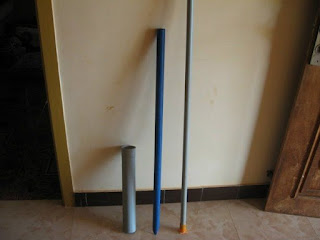
Step 3: 64 mm, 32 mm and 25 mm dia PVC pipes which  will be used for feeding the kitchen waste, guide pipe for the gas holder and guide pipe fixed with the digestion chamber respectively. A small piece of 32 mm dia pipe will be used as outlet for the slurry:

Step 4:

1.  items required for the gas delivery system: got these items from a hardware store


1. Ball valve : one no ( to adjust the gas flow)
2. 'T' joint : one no ( to connect the gas holder and the ball valve)
3. Cap to block one end of 'T' joint : one no
4. Coupling or Adapter : one no (to connect vertical end of 'T' in to the gas collector)
5. Nipple: one no (added to the coupling in to the gas collector)
6. Gas pipe (flexible) : two meters
7. Barb : one no (fitted with the gas pipe, to join with the Ball valve)
8. Clip : one no (used for crimping the barb with the gas pipe and make it leak-proof)
9. Teflon tape : one roll (used as thread tape in all joints)

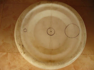
Step 5: Here I have marked the cuts to be made in the bottom of the gas collection tank. The smaller hole on the left for gas delivery system, center hole for fixing the 32 mm guide pipe and 64 mm hole for fixing the waste feeding pipe on the right side. Made these holes with the help of a sharp knife and hack saw blade.


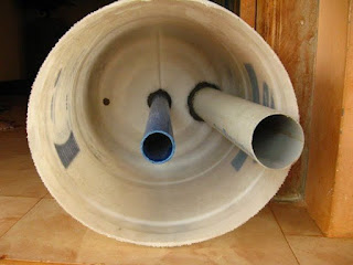
The next image is Inside of the gas holder showing the 32 mm guide pipe (center) and the 64 mm feeding pipe fixed with M-seal

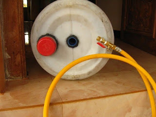
 Step 6: Top view of the gas holder showing the feeding pipe, central guide pipe and the gas delivery system: I have closed the feeding pipe withe an old lid  (red one). This will facilitate opening the feed pipe only during feeding the system.

Step 7: Digestion tank fitted with the central guide pipe and the outlet pipe for the slurry:

Step 8:

Completed unit. I have removed the gas pipe, so that the joints will get cured without any stress:
Step 9:

Charged the digester tank with cow dung diluted with water. Placed the gas holder tank and left it for two three days. The cow dung slurry started the process of gas forming.

Gas formation started and the gas holder tank gets lifted up. I have placed two bricks on top of the gas holder to get more gas pressure.
Step 10:
Note for students who are doing this as their School Project:

1. Take guidance from your teacher while using the gas in a stove or Bunsen burner.
2. Collect surplus food and wastage during lunch, dilute and feed the system.
3. Fruit peels, extracted tea powder, waste milk and milk products  can also be used for feeding the system.
4. DO NOT USE eggshells, Onion peels or left-over bones in this system as they will affect the efficient functioning of the system
5. Plant some seedling
6. while feeding, collect the slurry from the outlet, feed the seedlings and watch them grow

Wait for a day or two before feeding the system, allowing all joints to get cured and become leak-proof.

Initially, cow-dung mixed with water will be fed in to the system, which will start the gas formation process. Subsequently, food waste, decomposable organic material and kitchen waste will be diluted with water and used to feed the system. The gas holder will rise along the guide pipes based on the amount of gas produced. We can add some weight on top of the gas holder to increase the gas pressure. When we feed the system, the excess digested slurry will fall out through the outlet pipe, which can be collected, diluted and used as organic manure.

Initial production of gas will consist of oxygen, methane, carbon di oxide and some other gases and will not burn. These gases can be released to the atmosphere by opening the ball valve at least three / four times.

Subsequent gas will consist of about 70 to 80 percent methane and the rest carbon di oxide, which can be used in a single bio-gas burning stove or a Bunsen burner.

Total cost of this proto-type system is about one thousand Indian Rupees (about 20 dollars)

This is a basic prototype of a Bio-gas system using the food waste, decomposable organic material and kitchen waste to produce gas. An one thousand liter capacity Digestion tank will be sufficient for a small household for daily cooking purpose. The bigger commercial models provide a water seal between the digestion tank and gas holder tank.


You can get further information on kitchen waste based mini Bio-gas plant at the following links


http://www.instructables.com/id/Constructing-a-Medium-Sized-Biogas-Plant-Using-Kit/step3/Other-Materials-Required/