KITCHEN (FOOD)
WASTE---SMALL MODULAR BIO GAS SYSTEM FOR INDIVIDUAL HOUSES
How much Kitchen
Waste do we have to feed on daily basis?
Kitchen
waste is high calorie feedstock which contains starch, sugar, cellulose or
protein. This material is capable of producing more quantity of methane per ton
of feedstock (on dry weight basis). Care must be taken to ensure that kitchen
waste like vegetable pcs, leaves, wheat roti / bread or solid left overs are
converted in semi liquid form before feeding in the Plant. This can be done
either by using food crusher or keeping kitchen waste in Bucket with water for
4 to 5 hours prior to feeding.
DATA CHART :
Gas Generation Capacity
|
SIZE OF TANKS (PVC)
|
Mix Kitchen Waste / day
|
Water / day
|
Initial Cow Dung charging
|
DIA
|
HEIGHT
|
0.5 Cu. Mtr
|
1600
|
1100
|
2.5 Kg
|
2.5 Litrs of Water
|
20 Kg
|
1.0 Cu. Mtr
|
2100
|
1500
|
5 Kg
|
5 Litrs of Water
|
25 Kg
|
1.5 Cu. Mtr
|
2300
|
1650
|
10 Kg
|
10 Litrs of Water
|
30 Kg
|
2.0 Cu. Mtr.
|
2550
|
1800
|
20 Kg
|
20 Litrs of Water
|
35 Kg
|
Gas Volume :
One Cu. Mtr. Bio
Gas runs approximately 1 Hour at a time. One can cook
three meals per day by using 1 cum Bio Gas Plant.
We can use Bio Gas frequently about three times a day
with the interval of around 2 to 3 hours.1 cum of bio gas is equal to 0.43 kg
of LPG. About 5 kg. of kitchen waste is
required for 1 cum. plant. Gas coming out of the plant can be used in the
kitchen with the help of biogas stove while the slurry coming out from the
outlet can be used as manure. The gas generated will have 60 to 70% methane, 5
to 10% water vapour (moisture) and the balance will be Carbon-di-oxide.
How it works :
The main digester is initially fed with fresh cow dung
slurry so that slurry comes out from the slurry outlet pipe. The ratio of dung
and water should be 1:1 Subsequently, cattle dung is not needed. Now
wait for bio gas production to start in the newly installed plant. It may take
2-3 days for the first production of gas.
As gas starts producing, one can start feeding the plant
daily with kitchen / vegetable waste in
a small quantity and increase it to the recommended quantity after one week..
The ratio of kitchen waste and water should be 1:1.This will facilitate easy
flow of waste through inlet into the
bio-methanization plant. The
value of pH
of the kitchen
waste should be ideally kept at 7 for optimum production of biogas. Make a
slurry of lime by adding one kg lime with 10 liter of water and add it into the
digester chamber to make pH 7. Check with pH paper whether the pH is 7 or not
regularly.
LOCATION:
Always in a sunny area where temperature is high and as near to kitchen
as possible so that gas pipe length is less.
OPERATING COST : The operating cost of Bio Gas plant
is very less. All what required for 1
Cu. Mtr Bio Gas plant is 5 to 6 Kg of
Kitchen waste / on dry weight basis. Break even
period is approximately 5 to 6 years if Gas is used for cooking application
CONTACT US ENVO PROJECTS Mobile: 09899300371
Mini Bio-gas plant using food waste, decomposable organic material and kitchen waste
Source Of The Article: http://www.instructables.com/id/Bio-gas-plant-using-kitchen-waste/
Components of the Bio-gas Plant
The major components of the bio-gas plant are a digester tank, an inlet for feeding the kitchen waste, gas holder tank, an outlet for the digested slurry and the gas delivery system for taking out and utilizing the produced gas.
This project is also useful for students to have a hands-on learning experience in constructing a Mini Bio-Gas Plant, using locally available material.
Material Required:
1. Empty PVC can 50 ltrs capacity: 1 No. (to be used as Digester Tank)
2. Empty PVC can 40 ltrs capacity: 1 no. (to be used as Gas Holder Tank) (Make sure the smaller can fits inside larger one and moves freely)
3. 64 mm dia pvc pipe: about 40 cm long (to be used for feeding waste material)
4. 32 mm dia pvc pipe: about 50 cm long (fixed inside gas holder tank as a guide pipe)
5. 25 mm dia pvc pipe: about 75 cm long (fixed inside the digester tank as a guide pipe)
6. 32 mm dia pvc pipe: about 25 cm long (fixed on digester tank to act as outlet for digested slurry)
7. M-seal or any water-proof adeshive
8. Gas outlet system: Please see Step 4 below for required materials and construction
Tools required
Do not require many tools here. A hack saw blade for cutting the cans & pipes and a sharp knife for cutting holes on the cans are all the tools we need.
Additional accessories
A single burner bio-gas stove or a Bunsen Burner used in school laboratories
Initially, cow-dung mixed with water will be fed in to the system, which will start the gas formation process. Subsequently, food waste, decomposable organic material and kitchen waste will be diluted with water and used to feed the system. The gas holder will rise along the guide pipes based on the amount of gas produced. We can add some weight on top of the gas holder to increase the gas pressure. When we feed the system, the excess digested slurry will fall out through the outlet pipe, which can be collected, diluted and used as organic manure.
Initial production of gas will consist of oxygen, methane, carbon di oxide and some other gases and will not burn. These gases can be released to the atmosphere by opening the ball valve at least three / four times.
Subsequent gas will consist of about 70 to 80 percent methane and the rest carbon di oxide, which can be used in a single bio-gas burning stove or a Bunsen burner.
Total cost of this proto-type system is about one thousand Indian Rupees (about 20 dollars)
Gas formation started and the gas holder tank gets lifted up. I have placed two bricks on top of the gas holder to get more gas pressure.
Note for students who are doing this as their School Project:
1. Take guidance from your teacher while using the gas in a stove or Bunsen burner.
2. Collect surplus food and wastage during lunch, dilute and feed the system.
3. Fruit peels, extracted tea powder, waste milk and milk products can also be used for feeding the system.
4. DO NOT USE eggshells, Onion peels or left-over bones in this system as they will affect the efficient functioning of the system
5. Plant some seedling
6. while feeding, collect the slurry from the outlet, feed the seedlings and watch them grow
Read step by step instruction at: http://www.instructables.com/id/Bio-gas-plant-using-kitchen-waste/
Components of the Bio-gas Plant
The major components of the bio-gas plant are a
digester tank, an inlet for feeding the kitchen waste, gas holder tank, an
outlet for the digested slurry and the gas delivery system for taking out
and utilizing the produced gas.
This project is also useful for students to have
a hands-on learning experience in constructing a Mini Bio-Gas Plant, using
locally available material.
Material Required:
1. Empty PVC can 50 ltrs capacity: 1 No. (to be
used as Digester Tank)
2. Empty
PVC can 40 ltrs capacity: 1 no. (to be used as Gas Holder Tank) (Make sure
the smaller can fits inside larger one and moves freely)
3. 64 mm
dia pvc pipe: about 40 cm long (to be used for feeding waste material)
4. 32 mm
dia pvc pipe: about 50 cm long (fixed inside gas holder tank as a guide pipe)
5. 25 mm
dia pvc pipe: about 75 cm long (fixed inside the digester tank as a guide pipe)
6. 32 mm
dia pvc pipe: about 25 cm long (fixed on digester tank to act as outlet
for digested slurry)
7.
M-seal or any water-proof adeshive
8. Gas
outlet system: Please see Step 4 below for required materials and construction
Tools required
Do not require many tools here. A hack saw blade
for cutting the cans & pipes and a sharp knife for cutting holes on
the cans are all the tools we need.
Additional accessories
A single burner bio-gas stove or a Bunsen Burner
used in school laboratories
Initially,
cow-dung mixed with water will be fed in to the system, which will start the
gas formation process. Subsequently, food waste, decomposable organic material
and kitchen waste will be diluted with water and used to feed the system.
The gas holder will rise along the guide pipes based on the amount of gas
produced. We can add some weight on top of the gas holder to increase the gas
pressure. When we feed the system, the excess digested slurry will fall out
through the outlet pipe, which can be collected, diluted and used as organic
manure.
Initial production of gas will consist of
oxygen, methane, carbon di oxide and some other gases and will not burn. These
gases can be released to the atmosphere by opening the ball valve at
least three / four times.
Subsequent gas will consist of about 70 to 80
percent methane and the rest carbon di oxide, which can be used in a single
bio-gas burning stove or a Bunsen burner.
Total cost of this proto-type system is about
one thousand Indian Rupees (about 20 dollars)
Gas
formation started and the gas holder tank gets lifted up. I have placed two
bricks on top of the gas holder to get more gas pressure.
Note for students who are doing this as their School Project:
1. Take guidance from your teacher while using
the gas in a stove or Bunsen burner.
2.
Collect surplus food and wastage during lunch, dilute and feed the system.
3. Fruit
peels, extracted tea powder, waste milk and milk products can also be
used for feeding the system.
4. DO
NOT USE eggshells, Onion peels or left-over bones in this system as they will
affect the efficient functioning of the system
5. Plant
some seedling
6. while
feeding, collect the slurry from the outlet, feed the seedlings and watch them
grow
Step one; 50
ltrs capacity PVC can, which will act as the digester unit and removed the top
portion of the can, by cutting it with a hack saw blade:
Step 2: The smaller white can, which
will act as the gas holder fits inside the red one. Here, again removed the top
of the white can, also with the help of a hack saw blade:
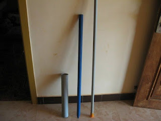
Step 3: 64 mm, 32 mm and 25 mm dia
PVC pipes which will be used for feeding the kitchen waste, guide pipe
for the gas holder and guide pipe fixed with the digestion chamber
respectively. A small piece of 32 mm dia pipe will be used as outlet for the
slurry:
Step 4:
1. items required for the gas delivery system:
got these items from a hardware store
1. Ball valve : one no ( to adjust the gas flow)
2. 'T' joint : one no ( to connect the gas
holder and the ball valve)
3. Cap to block one end of 'T' joint : one no
4. Coupling or Adapter : one no (to connect
vertical end of 'T' in to the gas collector)
5. Nipple: one no (added to the coupling in to
the gas collector)
6. Gas pipe (flexible) : two meters
7. Barb : one no (fitted with the gas pipe, to
join with the Ball valve)
8. Clip : one no (used for crimping the barb
with the gas pipe and make it leak-proof)
9. Teflon tape : one roll (used as thread tape
in all joints)
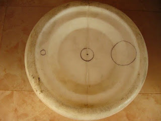
Step 5: Here I have marked the cuts
to be made in the bottom of the gas collection tank. The smaller hole on the
left for gas delivery system, center hole for fixing the 32 mm guide pipe and
64 mm hole for fixing the waste feeding pipe on the right side. Made these
holes with the help of a sharp knife and hack saw blade.
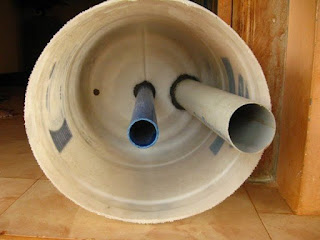
The next image is Inside of the gas holder
showing the 32 mm guide pipe (center) and the 64 mm feeding pipe fixed with
M-seal
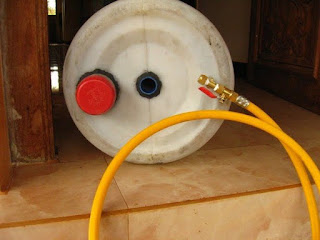
Step 6: Top view of the gas holder
showing the feeding pipe, central guide pipe and the gas delivery system: I
have closed the feeding pipe withe an old lid (red one). This will
facilitate opening the feed pipe only during feeding the system.
Step 7: Digestion tank fitted with
the central guide pipe and the outlet pipe for the slurry:
Step 8:
Completed
unit. I have removed the gas pipe, so that the joints will get cured without
any stress:
Step 9:
Charged the digester tank with cow dung diluted with water.
Placed the gas holder tank and left it for two three days. The cow dung slurry
started the process of gas forming.
Gas formation started and the gas holder tank
gets lifted up. I have placed two bricks on top of the gas holder to get more
gas pressure.
Step
10:
Note
for students who are doing this as their School Project:
1. Take guidance from your teacher while using the gas in a stove or Bunsen
burner.
2. Collect surplus food and wastage during lunch, dilute and feed the system.
3. Fruit peels, extracted tea powder, waste milk and milk products can
also be used for feeding the system.
4. DO NOT USE eggshells, Onion peels or left-over bones in this system as they
will affect the efficient functioning of the system
5. Plant some seedling
6. while feeding, collect the slurry from the outlet, feed the seedlings and
watch them grow
Wait for a day or two before feeding the system,
allowing all joints to get cured and become leak-proof.
Initially, cow-dung mixed with water will be fed
in to the system, which will start the gas formation process. Subsequently,
food waste, decomposable organic material and kitchen waste will be
diluted with water and used to feed the system. The gas holder will rise along
the guide pipes based on the amount of gas produced. We can add some weight on
top of the gas holder to increase the gas pressure. When we feed the system,
the excess digested slurry will fall out through the outlet pipe, which can be
collected, diluted and used as organic manure.
Initial production of gas will consist of
oxygen, methane, carbon di oxide and some other gases and will not burn. These
gases can be released to the atmosphere by opening the ball valve at
least three / four times.
Subsequent gas will consist of about 70 to 80
percent methane and the rest carbon di oxide, which can be used in a single
bio-gas burning stove or a Bunsen burner.
Total cost of this proto-type system is about
one thousand Indian Rupees (about 20 dollars)
This is a basic prototype of a Bio-gas system
using the food waste, decomposable organic material and kitchen waste to
produce gas. An one thousand liter capacity Digestion tank will be
sufficient for a small household for daily cooking purpose. The bigger
commercial models provide a water seal between the digestion tank and gas
holder tank.


You can get further information on kitchen waste based mini
Bio-gas plant at the following links
http://www.instructables.com/id/Constructing-a-Medium-Sized-Biogas-Plant-Using-Kit/step3/Other-Materials-Required/